
Installation guide
Installing the iSmart Module
Mount, wire, pair, commission. The parts that matter, in order.
Before you start
- Isolate all supplies at the breaker and verify dead before opening anything.
- Electrical work must be done by a person qualified under your local rules.
- This is automation, not a safety system — it does not replace a barrier, an alarm, or supervision.
- TODO — state the supply ratings, breaker and RCD/GFCI requirements.
Mount the enclosure
The housing hangs on its rear plate, so one person can position it, mark, and hang it without help. Choose a spot at the equipment pad with clear access to the front for service.
TODO — bracket dimensions, fixing centres, minimum clearances, and the torque for the fixings.
- TODO — confirm the mounting height and orientation.
- TODO — cable entry direction and gland sizes.
What is inside
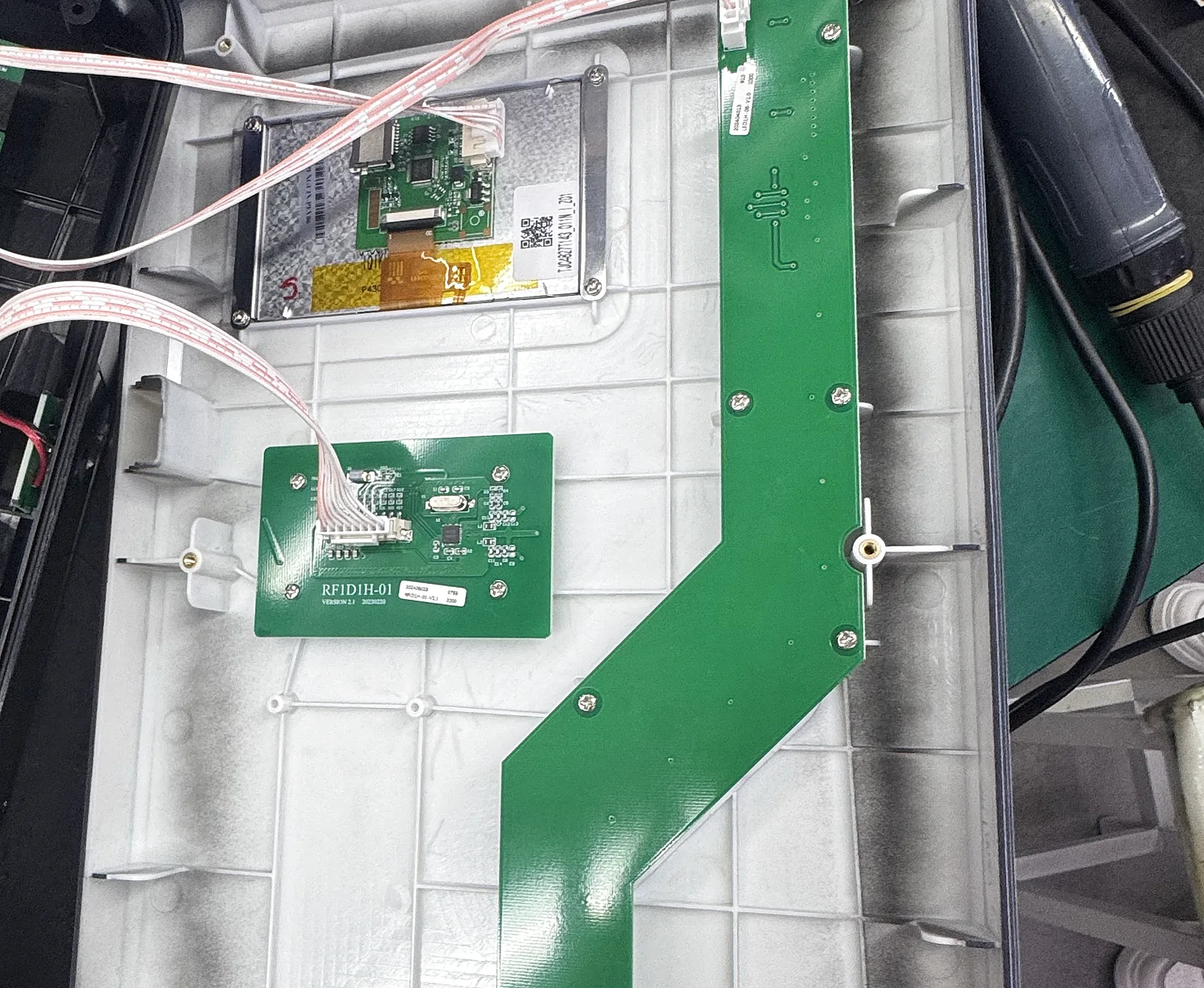
Behind the front panel the enclosure carries the 7-inch display, the light-guide board that drives the front strip, and the reader board. Ribbon cables run from the mainboard to each.
TODO — name each assembly as you refer to it in service, and note which connectors are keyed.
Wire the relay driver board
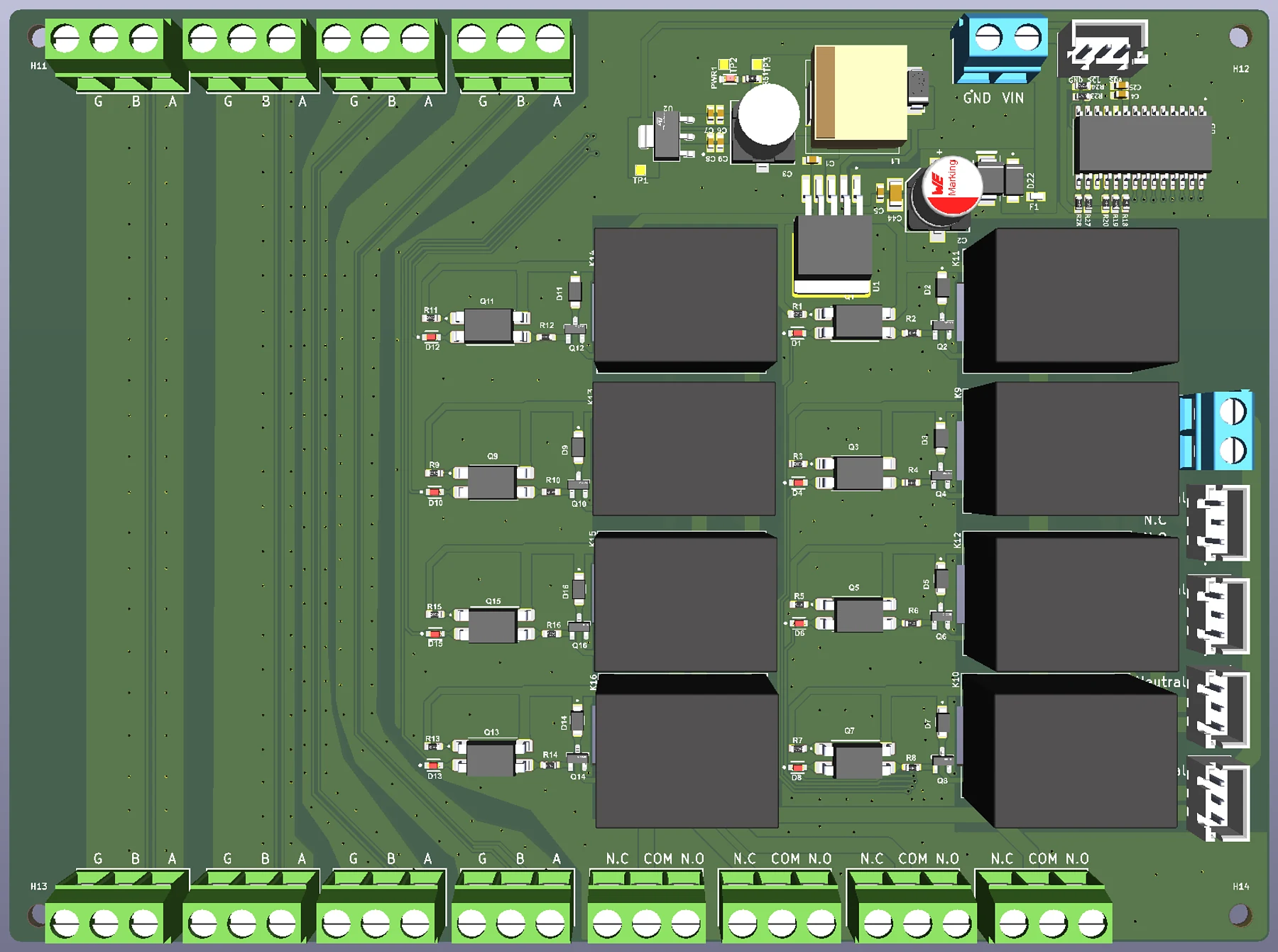
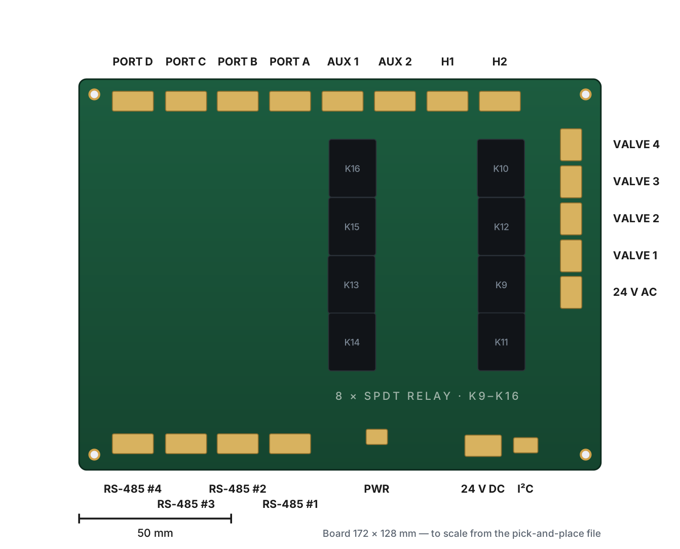
Field wiring lands on the relay driver board: eight SPDT relays for high-voltage loads, four RS-485 ports for equipment that speaks it, four valve-actuator outputs, and two auxiliary channels.
The map is drawn to scale from the board's pick-and-place file, so the positions match the physical board.
TODO — conductor sizes, torque values, and which loads belong on which relay.
Power and commissioning
The board takes 24 V AC and 24 V DC on separate terminals, with a fuse on the input. Bring power up before pairing so the module can be reached from the app.
TODO — the commissioning order, what the display shows on first boot, and how to verify each relay before handing over.
- TODO — first-boot checks.
- TODO — per-relay verification.
- TODO — where the device code is printed for pairing.
Terminal reference
Read from the relay driver board’s own BOM and pick-and-place files, so the designators match the silkscreen.
| Designator | Qty | What it is | Notes |
|---|---|---|---|
| K9–K16 | 8 | SPDT relay outputs | Omron G5LE-14-DC5 · N.C / COM / N.O per channel |
| RS485_1–4 | 4 | RS-485 ports | G / B / A per port |
| VALV1–4 | 4 | Valve actuator outputs | JST B3B-XH-A 3-pin |
| PORTA1–PORTD1 | 4 | Expansion ports | G / B / A per port |
| AUX1, AUX2 | 2 | Auxiliary channels | TODO — confirm intended use |
| H1, H2 | 2 | Header connectors | TODO — confirm function |
| 24VAC1 | 1 | 24 V AC input | CUI TB002-500-02BE terminal block |
| 24VDC1 | 1 | 24 V DC input | CUI TB002-500-02BE terminal block |
| I2C1 | 1 | I²C expansion | JST B3B-XH-A |
| F1 | 1 | Input fuse | 0686F1000-01 |
| U-series | 3 | I/O expander & regulator | MCP23017 I/O expander · LM2575HV switcher |