
Hayward Universal H-Series Heaters
Universal H-Series heaters have no data bus. They are driven by a voltage-free contact across two terminals — the classic fireman's switch — which makes the iSmart Module the thermostat rather than just the messenger.
Why this one is a relay, not a bus
The pumps connect over RS-485. Universal H-Series heaters do not — there is no RS-485 or automation port anywhere in the range. The only external control Hayward provides is a remote connection terminal block that expects a switch closure. So the heater lands on one of the iSmart Module's heater relay outputs rather than on a PORT terminal, and none of the RS-485 rules on the pump page apply here.
Hayward supports two arrangements on that block: a 2-wire remote thermostat, and a 3-wire remote switch that lets an external control pick Pool or Spa. The iSmart Module uses the 2-wire arrangement.
The heater's remote terminal block
The block sits in the lower compartment inside the junction box — field power wiring goes to a separate block in the upper compartment, so do not confuse the two. The heater has a junction box on each side; use one of them for the remote wiring, not both. It carries three terminals, identified by the colour of the factory wire already landed on each.
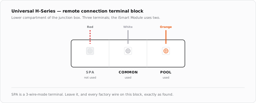
| Terminal | Factory wire | Used? | Role |
|---|---|---|---|
| POOL | Orange | Yes | Heat-call leg, switched by the iSmart Module |
| COMMON / 24V | White | Yes | Return leg — the heater's own 24 V |
| SPA | Red | No | 3-wire mode only; leave as found |
The iSmart Module side
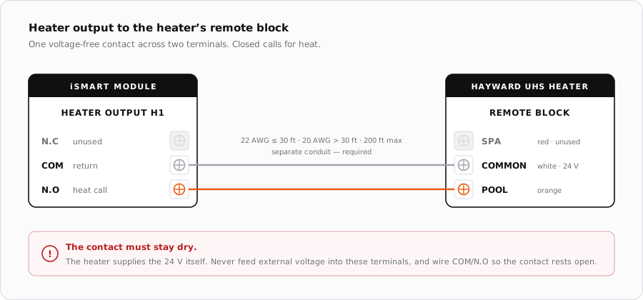
Use a heater relay output — H1 or H2. Each is a three-pole block bringing out one relay's dry contacts as N.C, COM and N.O, driven through an optocoupler so the contact is fully isolated from the board's logic. Wire COM and N.O, leaving N.C unused, so the contact rests open: no heat call when the relay is de-energised or the module is powered down.
Cable
- 22 AWG for runs under 30 ft; 20 AWG for runs over 30 ft.
- 200 ft is the maximum run Hayward allows.
- Run the remote wiring in its own conduit, separate from the heater's power wiring. Hayward requires this — it is not a best-practice suggestion.
- No shield or twisted pair is needed. This is a contact closure, not a data pair.
Putting the heater into bypass mode
A 2-wire remote thermostat only works once the heater has been told to expect one. That is bypass mode, and the heater confirms it by displaying the code “bo”.
- 1
Wire both conductors first
Land POOL and COMMON at the heater and COM/N.O at the iSmart Module, then close up and restore power to the heater.
- 2
Select STANDBY
Press the MODE key on the heater keypad until the control is in STANDBY. The STANDBY LED lights.
- 3
Enable bypass
Press and hold the DOWN and MODE keys together for 3 seconds, until the display shows the code “bo”. That is the configuration step, and it only needs doing once.
- 4
Return the heater to an operating mode
Press MODE to leave STANDBY and select POOL (or SPA). This matters: the heater will not respond to the remote thermostat while it sits in STANDBY. The display shows “bo” and the POOL or SPA LED stays lit.
- 5
Prove the contact
Call for heat from NexPool Connect. The heater should start its ignition sequence within a few seconds. Release the call and confirm it shuts down.
Who owns the temperature
This is the part worth being explicit about with a customer. In 2-wire mode the heater is not deciding when to run — the iSmart Module is. The module reads water temperature, compares it against the set point in the app, and closes the contact when heat is wanted. The heater simply obeys.
The heater keeps one job: it caps water temperature at 104 °F regardless of what the remote thermostat asks for. That limit is the heater's, it cannot be raised from the app, and it is the safety backstop behind whatever the module requests.
When it does not fire
| Symptom | Where to look first |
|---|---|
| Nothing happens on a heat call | Heater still in STANDBY. Bypass is configured from STANDBY but the heater must be returned to POOL or SPA to run. |
| Display shows a temperature, not “bo” | Bypass mode was never enabled. Repeat the DOWN + MODE hold for 3 seconds. |
| Heater runs constantly | Contact wired across N.C instead of N.O, so it rests closed. Move it to N.O. |
| Heater fires but cuts out early | Water flow or the heater's own limits, not the control wiring — the contact only requests heat, it does not override any interlock. |
| Intermittent operation on a long run | Undersized conductors or the remote cable sharing conduit with power wiring. |
| Will not exceed 104 °F | Expected. That ceiling belongs to the heater and cannot be lifted from the app. |
Sources
- Hayward, Universal H-Series Service & Installation Manual — remote connection terminal block, 2-wire remote thermostat procedure, bypass (“bo”) mode, conductor sizing and maximum run
- iSmart Module relay driver board — KiCad schematic, “Heater Relay Drivers” sheet (K13/K14 to H1/H2, optocoupled, N.C / COM / N.O dry contacts) and board BOM