
TriStar, MaxFlo and Super Pump — RS-485 wiring
Hayward's variable-speed pumps accept speed and schedule commands over a three-wire RS-485 bus. This guide covers landing that bus on the iSmart Module, addressing the pump, and proving the link before you walk away.
Check your pump can be driven externally
External control is a per-model feature, not a per-family one. Some pumps in these ranges expose an RS-485 automation port and some are standalone units with a keypad only — a MaxFlo VS, for instance, may have no external control capability at all depending on the part number. Read the model number off the motor label and check it against Hayward's own documentation before you quote the job.
Where the pump does support it, Hayward ships the tail you need as the SPX3200DRCC Communication Cable Kit: a moulded plug for the pump end and bare conductors for the controller end.
What the iSmart Module gives you
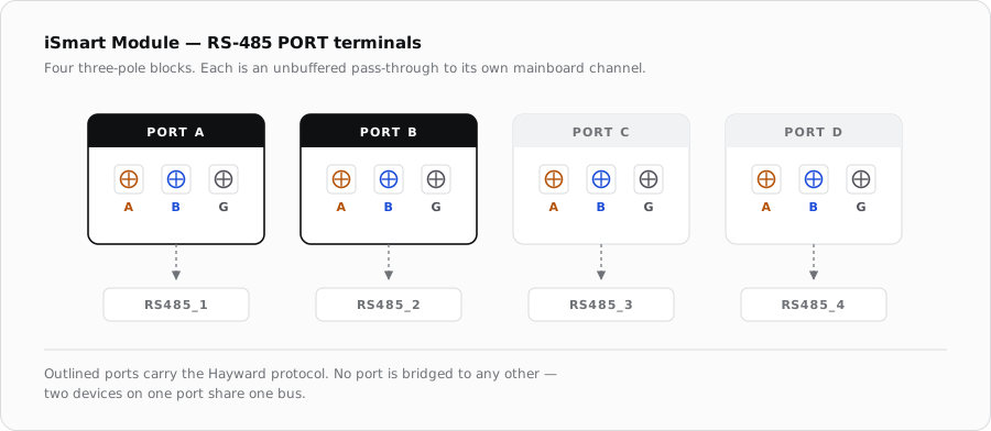
The iSmart Module brings out four RS-485 terminals — PORT A, PORT B, PORT C and PORT D. Each is a three-pole pluggable screw block carrying A, B and G, and each one is wired straight through to its own independent serial channel on the mainboard. There is no repeater and no bridging between them: PORT A and PORT B are two electrically separate buses.
The pin mapping
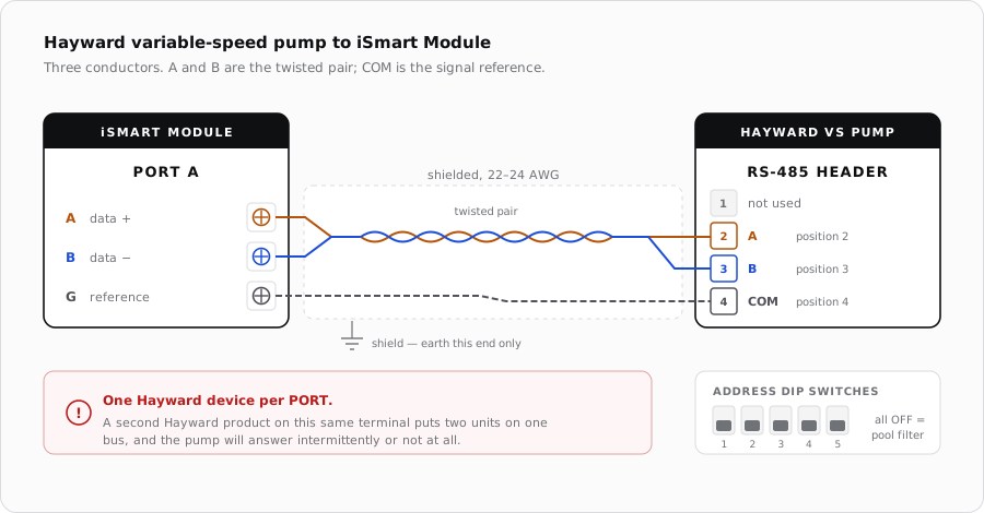
Hayward's automation connector is a four-position header, and only three of its positions carry the bus. Hayward labels them by position number; the iSmart Module labels its terminals by signal. Wire them like this:
| Hayward pump | Position | iSmart Module | Function |
|---|---|---|---|
| A | 2 | A | Non-inverting data line |
| B | 3 | B | Inverting data line |
| COM | 4 | G | Signal reference / common |
| — | 1 | — | Not used for automation |
Cable
- Two twisted pairs or one twisted pair plus a drain, 22–24 AWG, shielded.
- A and B must be the two halves of the same twisted pair. Splitting them across pairs is the single most common cause of a flaky bus.
- Ground the shield at the iSmart Module end only. Grounding both ends invites a circulating current through the shield.
- Run it separately from the 230 VAC feed. Where a crossing is unavoidable, cross at a right angle rather than running alongside.
- Daisy-chain, never star. A spur off the middle of the run is a stub, and stubs reflect.
Wiring it up
- 1
Kill the power
Open the breaker feeding the pump and verify the pump is dead. Power down the iSmart Module as well before you insert or remove a PORT plug.
- 2
Open the pump's electrical compartment
Remove the cover to expose the drive board. You will find the existing RS-485 connector and the display wires already fitted.
- 3
Free up the automation connector
Unplug the RS-485 connector carrying the display wires from the board and move it aside, then fit the additional RS-485 connector supplied in the cable kit. Set the address dip switches now, while the board is accessible.
- 4
Terminate the control cable at the pump
Land A on position 2, B on position 3 and COM on position 4. Watch the orientation of the connector — it is easy to fit a four-way plug reversed.
- 5
Terminate at the iSmart Module
Pull the plug out of PORT A, land A, B and G on the matching screw poles, torque them down and reseat the plug. Tug each conductor to check it is held.
- 6
Dress and restore power
Close the pump compartment, secure the cable clear of the mains feed, then power up the iSmart Module first and the pump second.
Addressing the pump
The pump takes its address from a block of dip switches on the drive board. Hayward publishes one table for its own Omni-family controllers, where the switches are left alone, and another for third-party and legacy controllers, where you set them. The iSmart Module is a third-party controller, so use the table below.
| Address | SW 1 | SW 2 | SW 3 | SW 4 | SW 5 |
|---|---|---|---|---|---|
| Pool filter | OFF | OFF | OFF | OFF | OFF |
| Aux 1 / spa filter | OFF | ON | OFF | OFF | OFF |
| Aux 2 | OFF | OFF | ON | OFF | OFF |
| Aux 3 | OFF | ON | ON | OFF | OFF |
| Aux 4 | OFF | OFF | OFF | ON | OFF |
| Aux 5 | OFF | ON | OFF | ON | OFF |
| Aux 6 | OFF | OFF | ON | ON | OFF |
| Aux 7 | OFF | ON | ON | ON | OFF |
| Aux 8 | OFF | OFF | OFF | OFF | ON |
A single pump on its own PORT should be set to Pool filter. Use the auxiliary addresses when a second pump — a spa or water-feature pump — is on a different PORT and you need the two to stay distinguishable in the app.
Proving the link
- Open the pump in NexPool Connect and command a low speed. The motor should change note within a couple of seconds.
- Command a second, higher speed. A pump that accepts one speed but not another is usually an addressing mismatch rather than a wiring fault.
- Check that RPM and power draw are reported back. Commands going out with nothing coming back points at one of the two data conductors.
When it does not come up
| Symptom | Where to look first |
|---|---|
| No response at all | A and B swapped — the commonest fault, and harmless to correct. Then check the plug is fully seated at both ends. |
| Works, then drops out | A and B split across two different twisted pairs, a shield grounded at both ends, or the cable run alongside the mains feed. |
| Pump ignores some commands | Dip-switch address does not match what the controller expects. Re-check against the table above. |
| Two Hayward devices, one erratic | Both are on the same PORT. Move one to its own PORT. |
| Pump display blank and no control | Distinguish a real fault from the normal blank display above: if the pump also will not respond, verify the display wires are secure on the RS-485 bus and that supply voltage is within 10% of nominal. |
Sources
- Hayward, TriStar VS Variable Speed Pump Technical Training Guide (TSG-HCPSSa) — pin mapping, dip-switch address table, commissioning behaviour
- iSmart Module relay driver board — KiCad schematic, “RS485 Pass Through” sheet, and board BOM (PORT A–D, A/B/G terminal order, no termination fitted)